Galaxy Reader Wiring QRG 
1.0 Wiegand Reader - Cable Specs & Wiring
-
5-conductor, 22 AWG, overall shielded; max cable distance is 500 feet.
-
Reader will require separate power supply if the current draw is over 150 mA.
-
Ground the Drain-wire at one end only - at the DRM Board (GND).
-
Refer to reader manufacturer’s instructions for wiring (manufacturer's specs may supersede Galaxy specs).
|
635-DRM Terminal Functions (PN 20-0263-10) |
Wiegand Reader |
|
|---|---|---|
|
LED |
(LED control line) |
LED Control |
|
D 1 |
(Data 1) |
DATA 1 |
|
VDC |
(+12 VDC) ( for +5 VDC use Regulator PN 92-3001-05 ) |
VDC |
|
GND |
(Power Supply Ground) |
GND |
|
D 0 |
(Data 0) |
DATA 0 |
2.0 ABA Reader - Cable Specs & Wiring
-
5-conductor, 22 AWG, overall shielded; max cable distance is 500 feet.
-
Reader will require separate power supply if the current draw is over 150 mA.
-
Ground the Drain-wire at one end only - at the DRM Board (GND).
-
Refer to reader manufacturer’s instructions for wiring (manufacturer's specs may supersede Galaxy specs).
|
635-DRM Terminal Functions (PN 20-0263-10) |
ABA Reader |
|
|---|---|---|
|
LED |
(LED control line) |
LED Control |
|
D 1 |
(Data 1) |
DATA 1 |
|
VDC |
(+12 VDC) ( for +5 VDC use Regulator PN 92-3001-05 ) |
VDC |
|
GND |
(Power Supply Ground) |
GND |
|
D 0 |
(Data 0) |
CLOCK |
3.0 Biometric Reader - Cable Specs & Wiring
-
5-conductor, 22 AWG, overall shielded; max cable distance is 500 feet.
-
Cat-5e Ethernet cable for TCP/IP communication back to the server; max cable distance 300 feet.
-
Reader will require separate power supply if the current draw is over 150 mA.
-
Ground the Drain-wire at one end only - at the DRM Board (GND).
-
Refer to reader manufacturer’s instructions for wiring (manufacturer's specs may supersede Galaxy specs)
-
See next section for information on IDEMIA Morpho Sigma Readers.
|
635-DRM Terminal Functions (PN 20-0263-10) |
Wiegand Reader |
|
|---|---|---|
|
LED |
(LED control line) |
LED Control |
|
D 1 |
(Data 1) |
DATA 1 |
|
VDC |
(+12 VDC) ( Do not use for reader power! ) |
VDC |
|
GND |
(Power Supply Ground) |
GND |
|
D 0 |
(Data 0) |
DATA 0 |
4.0 BridgePoint Reader (NON-FICAM)
-
5-conductor, 22 AWG, overall shielded; max cable distance is 500 feet.
-
2-conductor- twisted pair, 22 AWG max cable distance 500 feet (for Mode/Factor Control)
-
Reader will require separate power supply if the current draw is over 150 mA. You must common reader P.S. ground to controller ground.
-
Ground the Drain-wire at one end only - at the DRM Board (GND).
-
Refer to reader manufacturer’s instructions for wiring (manufacturer's specs may supersede Galaxy specs).
-
Min. Board Requirement: 635-DRM Board (Dual Reader Module) – PN 20-0263-10
-
DRM Relay-2 must be use for Mode/Factor Control
MODES/FACTORS:
-
Mode 1 Card Only (high)
-
Mode 2 Card + Pin (low)
NOTES:
-
Mode signal line High (unconnected) for 1-Factor Card Only.
-
Mode signal line Low (connected to ground) for 2-Factor Card + Pin.
-
Place a schedule on Relay-2 in System Galaxy Reader Properties - to alternate Mode/Factor.
|
635-DRM Terminal Functions (PN 20-0263-10) |
BridgePoint Wiegand Reader |
|
|---|---|---|
|
LED |
(LED control line) |
LED1 |
|
D 1 |
(Data 1) |
WEG 1 |
|
VDC |
(+12 VDC) ( Do not use for reader power! ) |
VDC (to separate power supply) |
|
GND |
(Power Supply Ground) |
GND (common to controller ground) |
|
D 0 |
(Data 0) |
WEG 0 |
|
635-DRM RELAY-2 |
BridgePoint Mode/Factor |
|
|---|---|---|
|
COM |
(must tie to reader’s power supply ground) |
- - - |
|
NO |
(to mode control line) |
LED 2 |
5.0 IDEMIA (Morpho) SIGMA Biometric Reader - Cable Specs & Wiring
-
3-conductor, 20 - 24 AWG, overall shielded; non-stranded; max cable distance is 500 feet.
-
2-conductor, 16 AWG for at +12vdc (18 AWG for +24vdc) for 500 feet distance. Reader draws 1A at 12v (0.5A at 24v).
-
Cat-5e Ethernet cable for TCP/IP communication back to the server; max cable distance 300 feet.
-
Separate power supply required (current draw is 1A). You must common the reader's power supply ground to controller ground.
-
Ground the drain-wire at one end only - land drain wire at the DRM Board (GND).
-
Refer to reader manufacturer’s instructions for wiring (manufacturer's specs may supersede Galaxy specs).
-
635-DRM Board (Dual Reader Module) – PN 20-0263-10
-
DRM Relay-2 is used to control Sigma “Wait for Panel Decision” for Voice/Prompt synchronization.
NOTES:
-
“Wait for Panel Decision”: Connect Sigma LED1 to the ‘NO’ leg of Relay-2. Tie the ‘COM’ leg of Relay-2 to DRM GND.
-
Set Relay-2 for Timed Mode (1 to 2 secs) and “Valid Unlock” checkbox must be "checked" in Reader Properties screen in the System Galaxy software.
|
635-DRM Terminal Functions (PN 20-0263-10) |
Wiegand Reader |
|
|---|---|---|
|
LED |
(LED control line) |
|
|
D 1 |
(Data 1) |
WIEG DATA 1 |
|
VDC |
(+12 VDC) ( Do not use for reader power! ) |
VDC (to separate power supply) |
|
GND |
(Power Supply Ground) |
GND (common to controller ground) |
|
D 0 |
(Data 0) |
WIEG DATA 0 |
|
635-DRM RELAY-2 |
SIGMA “Wait for Panel Decision” |
|
|---|---|---|
|
COM |
(must tie to reader’s power supply ground) |
- - - |
|
NO |
(for voice/prompt control line) |
LED 1 |
6.0 Invixium (IXM) Biometric Reader - Cable Specs & Wiring
-
3-conductor, 22 AWG, overall shielded; non-stranded; max cable distance is 500 feet.
-
2-conductor, 18 AWG for at +12vdc for 500 feet distance. Reader draws 1A at 12v .
-
Cat-5e Ethernet cable for TCP/IP communication back to the server; max cable distance 300 feet.
-
Separate power supply required (current draw is 1A). Must common reader's p.s. ground to controller ground.
-
Ground the drain-wire at one end only - land drain wire at the DRM Board (GND).
-
Refer to reader manufacturer’s instructions for wiring (manufacturer's specs may supersede Galaxy specs).
-
635-DRM Board (Dual Reader Module) – PN 20-0263-10
-
635-DRM LED is used to control reader’s for Voice Command when configured for “Wait for Panel Decision”.
NOTES:
-
The IXM Reader must be configured to “follow panel decision” in the IXM-WEB software in reader configuration screen.
-
Galaxy controller must be set for Door Lock = Steady-High; Door Unlock = Steady-Low in the LED Options tab of the Loop/Cluster Properties screen.
|
635-DRM Terminal Functions (PN 20-0263-10) |
Invixium Reader |
|
|---|---|---|
|
LED |
(LED control line) |
ACP LED1 (control Voice Command) |
|
D 1 |
(Data 1) |
WIEG DATA 1 |
|
VDC |
(+12 VDC) ( Do not use for reader power! ) |
|
|
GND |
(Power Supply Ground) |
VIN GND (bond to controller ground) |
|
D 0 |
(Data 0) |
W DATA Out 0 |
|
VIN + (VDC) to separate power supply |
||
|
VIN – (GND) to separate power supply |
||
7.0 SCM Reader (NON-FICAM)
-
5-conductor, 22 AWG, overall shielded max cable distance 500 feet.
-
2-conductor- twisted pair, 22 AWG, max cable distance 500 feet (for Mode/Factor Control).
-
Reader will require separate power supply if the current draw is over 150 mA.
-
You must common reader P.S. ground to controller ground.
-
Ground the Drain-wire at one end only (at the DRM Board “GND”).
-
Refer to reader manufacturer’s instructions for wiring (manufacturer's specs may supersede Galaxy specs)
-
Min. Board Requirement: 635-DRM Board (Dual Reader Module) – PN 20-0263-10
-
DRM Relay-2 must be use for Mode/Factor Control.
MODES/FACTORS
-
Mode 1 Card Only
-
Mode 2 Card + Pin
NOTES:
-
Mode signal line = High (unconnected) for 2-Factor Card + Pin.
-
Mode signal line = Low (connected to ground) for 1-Factor Card Only, the
-
Place a schedule on Relay-2 in System Galaxy Reader Properties to alternate Mode/Factor.
|
635-DRM Terminal Functions (PN 20-0263-10) |
SCM Reader |
|
|---|---|---|
|
LED |
(LED control line) |
LED Control |
|
D 1 |
(Data 1) |
D 1 |
|
VDC |
(+12 VDC) ( Do not use for reader power! ) |
VDC (to separate power supply) |
|
GND |
(Power Supply Ground) |
GND (common to controller ground) |
|
D 0 |
(Data 0) |
D 0 |
|
635-DRM RELAY-2 |
SCM Mode/Factor |
|
|---|---|---|
|
COM |
(must tie to reader’s power supply ground) |
REL 2 |
|
NO |
(to mode control line) |
RELGRN |
8.0 STid Easyline Reader
-
5-conductor, 22 AWG, overall shielded max cable distance 500 feet.
-
2-conductor- twisted pair, 22 AWG, max cable distance 500 feet.
-
Reader will require separate power supply if the current draw is over 150 mA
-
You must common reader P.S. ground to controller ground.
-
Ground the Drain-wire at one end only (at the DRM Board “GND”).
-
Min. Board Requirement: 635-DRM Board (Dual Reader Module) – PN 20-0263-10
-
Refer to the reader manufacturer’s instructions for wiring (manufacturer's specs may supersede Galaxy specs).
IMPORTANT NOTICES
-
Easyline PC2 Readers are configured to only read STid PC2 encoded smart cards.
No other smart cards can be read by this reader. -
The STid Reader with Proximity Module (acts as pass-through data) can read 125KHz cards (EM/ HID PROX/ AWID/ IOPROX/ INDALA), in addition to the 13.56 MHz STid PC2 Smart Cards.
-
Do not mix non-mobile STid Readers with mobile-enabled (Blue) STid Readers in the same system.
-
The mobile-enabled (Blue) STid Readers can only use the free Green Mobile ID (Mobile app).
-
Before power is applied, you must connect all accessory and field wiring, and firmly mount the reader to the wall.
-
The tamper switch is an accelerometer and is calibrated upon power up. If the reader is moved after being powered up, the reader will be in a ‘tamper’ state and will not send the correct 26 -bit Wiegand data but will send 30-bit data to indicate tamper state.
|
635-DRM Terminal Functions (PN 20-0263-10) |
STid Easyline Reader |
|
|---|---|---|
|
LED |
(LED control line) |
LED Control |
|
D 1 |
(Data 1) |
D 1 |
|
VDC |
(+12 VDC) |
VDC |
|
GND |
(common Reader’s p.s. ground to Controller ground) |
GND (common to controller ground) |
|
D 0 |
(Data 0) |
D 0 |
9.0 STid Reader with Galaxy Configuration
-
5-conductor, 22 AWG, overall shielded max cable distance 500 feet.
-
2-conductor- twisted pair, 22 AWG, max cable distance 500 feet.
-
Reader will require separate power supply if the current draw is over 150 mA.
-
You must common reader P.S. ground to controller ground.
-
Ground the Drain-wire at one end only (at the DRM Board “GND”).
-
Min. Board Requirement: 635-DRM Board (Dual Reader Module) – PN 20-0263-10
-
Refer to the reader manufacturer’s instructions for wiring (manufacturer's specs may supersede Galaxy specs).
IMPORTANT NOTICES:
-
STid Readers are configured to only read MIFARE/DESFIRE CSN.
-
PC2 Smart Cards: STid Reader can read the CSN from PC2 smart cards but cannot read the secure area.
-
The STid Reader with Proximity Module (acts as pass-through data) can read 125kHz cards (EM + HID PROX + AWID + IOPROX + INDALA), in addition to the 13.56 MHz. MIFARE/DESFIRE.
-
The mobile-enabled (Blue) STid Readers can use the Green, Yellow, and Blue Mobile ID (Mobile app).
-
Before power is applied, you must connect all accessory and field wiring, and firmly mount the reader to the wall.
-
The tamper switch is an accelerometer and is calibrated upon power up. If the reader is moved after being powered up, the reader will be in a ‘tamper’ state and will not send the correct 40 -bit Wiegand data but will send 44-bit data to indicate tamper state.
|
635-DRM Terminal Functions (PN 20-0263-10) |
STid Galaxy-Configured Reader |
|
|---|---|---|
|
LED |
(LED control line) |
LED Control |
|
D 1 |
(Data 1) |
D 1 |
|
VDC |
(+12 VDC) ( Use separate p.s. for reader power! ) |
VDC (to separate power supply) |
|
GND |
(common Reader’s p.s. ground to Controller ground) |
GND (common to controller ground) |
|
D 0 |
(Data 0) |
D 0 |
10.0 Veridt Stealth Series Reader (FICAM Solution for Technologies Industry)
-
5-conductor 22 AWG overall shielded; max cable distance 500 feet
-
2-conductor Twist pair, 22 AWG, max line distance 4000 feet (RS-485 Comm. for Mode/Factor Control)
-
A separate Power Supply is required (reader draws 400 mA at +12vdc).
-
Must common reader's power supply ground to controller ground.
-
Ground the Drain-wire at one end only - at the DRM Board (GND).
-
Refer to reader manufacturer’s instructions for wiring (manufacturer's specs may supersede Galaxy recommendations).
-
Min. Board Requirement: 635-DSI Board (Dual Serial Interface) PN 20-0665-10 – for Mode/Factor Control
|
READER MODES/FACTORS |
|
EWAC to 635 DRM Wiring Pinout |
||
|---|---|---|---|---|
|
Mode 1 Card Only |
|
EWAC Module |
635 DRM |
|
|
Mode 2 Card + Pin |
|
GND |
- - - - - - - |
GND |
|
Mode 3 Card + Pin + Bio |
|
D0 |
- - - - - - - |
D0 |
|
|
|
D1 |
- - - - - - - |
D1 |
|
|
|
I/O |
- - - - - - - |
LED |
|
|
|
NC |
- - - - - - - |
Not Used |
-
Install System Galaxy (SG) software according to Galaxy documentation.
-
Validate WEB API by using address: http://localhost:8000/swagger.
-
Also verify the GCS DataLoader Service is running on the Galaxy Comm/Event Server.
-
When you add the 635-Series Clusters into the SG Loop/Cluster Properties screen, do the following …
|
On the Advanced tab, set the Card Data Mode droplist to “Extended Card (256 Bits)”. |
|
|---|---|
|
On the LED Options tab, set LED States: DOOR Locked = ‘Steady High’ DOOR Unlocked = ‘Steady Low’ |
|


-
In the SG Reader Properties screen, configure the Reader Type field to ‘Standard Wiegand’.
-
In the SG Access Group Properties screen, you must create the Access Groups you will need.
-
In the SG Access Profile Properties screen, you must create 1 or more Access Profiles by assigning your access groups to the profile, based on your system needs.
-
Install the Galaxy 635-series Controller hardware according to Galaxy documentation.
-
In the controller, be sure to enable Extended Card Mode (set to “yes” in lower case).
-
Be sure to configure the correct IP Address for the Event Server.
-
-
Install the Technology Industries (TI) FICAM software per the manufacturer’s documentation.
-
from the SG Cardholder screen perform a card lookup of the GOV. ID CARD to validate that it is correctly pushed from the TI FICAM Software into System Galaxy database.
-
Install Veridt Reader and EWAC Module according to the manufacturer’s documentation.
-
Connect the EWAC Module to the Galaxy Model 635 DRM (Dual Reader Module) using the wiring pinout in the table above.
11.0 Veridt Stealth Series Readers (NON-FICAM)
-
5-conductor 22 AWG overall shielded; max cable distance 500 feet.
-
2-conductor Twist pair, 22 AWG, max line distance 4000 feet (RS-485 Comm. for Mode/Factor Control)
-
Separate Power Supply required (reader draws 400 mA at +12vdc). Common reader's power supply ground to controller ground.
-
Ground the Drain-wire at one end only - at the DRM Board (GND).
-
Refer to reader manufacturer’s instructions for wiring (manufacturer's specs may supersede Galaxy recommendations).
-
Min. Board Requirement: 635-DRM Board (Dual Reader Module) – PN 20-0263-10
-
Min. Board Requirement: 635-DSI Board (Dual Serial Interface) – PN 20-0665-10 – for Mode/Factor Control
|
635-DRM Terminal Functions (PN 20-0263-10) |
Veridt Reader |
|
|---|---|---|
|
LED |
(LED control line) |
LED Control * required |
|
D 1 |
(Data 1) |
DATA 1 |
|
VDC |
(+12 VDC) (Do not use for reader power!) |
VDC (to separate power supply) |
|
GND |
(Power Supply Ground) |
GND (common to controller ground) |
|
D 0 |
(Data 0) |
DATA 0 |
|
635-DSI Terminal Functions (PN 20-0665-10) |
Veridt Reader RS-485 Mode |
|
|---|---|---|
|
A+ |
RS-485 Data |
Yellow wire |
|
B - |
RS-485 Data |
Blue wire |
NOTES:
-
DSI Section used for Mode/Factor Control must be set to “Veridt CAC Reader” in System Galaxy Serial Channel Properties.
-
LED Option must be set for Door Locked “Steady High” and Door Unlocked “Steady Low” in System Galaxy Loop Properties.
-
Install System Galaxy (SG) software according to Galaxy documentation.
-
When you add the 635-Series Clusters into the SG Loop/Cluster Properties screen, do the following …
|
On the Advanced tab, set the Card Data Mode droplist to “Extended Card (256 Bits)”. |
|
|---|---|
|
On the LED Options tab, set LED States: DOOR Locked = ‘Steady High’ DOOR Unlocked = ‘Steady Low’ |
|
-
Open the DSI Serial Channels Properties screen from the SG menu Configure > Hardware, Serial Channels as follows:
-
Select the appropriate DSI Board Section (Section 1 or 2) that will support the CAC readers.
-
Set the Section Use field to the “Veridt CAC Reader”.
-
Once the Section is set for CAC Readers, set the CAC Mode you want (i.e., Card Only, Card+PIN, or Card+PIN+BIO).
-
-
In the SG Reader Properties screen, configure the Reader Type field to ‘Standard Wiegand’.
-
Install the Galaxy 635-series Controller hardware according to Galaxy documentation.
-
In the controller, be sure to enable Extended Card Mode (set to “yes” in lower case).
-
Be sure to configure the correct IP Address for the Event Server.
-
READER MODES/FACTORS
-
Mode 1 Card Only
-
Mode 2 Card + Pin
-
Mode 3 Card + Pin + Bio
-
You can change Reader Mode in the System Galaxy software by clicking the CAC button on the System Galaxy toolbar. Then select the desired Reader Mode from the Mode droplist and click the OK button in the pop-up dialog window.

12.0 635-DRM (PN 20-0263-10) – FULL SECTION TERMINAL PINOUT
Each Reader Section has the following terminals…
READER WIRING (9-PIN CONNECTOR)
-
5-conductor, 22 AWG, overall shielded; max cable distance is 500 feet.
-
Reader may require separate power supply if the current draw is over 150 milli Amps.
-
Ground the Drain-wire at one end only - at the DRM Board (GND).
-
Refer to reader manufacturer’s instructions for wiring (manufacturer's specs may supersede Galaxy specs).
|
635-DRM Terminal Functions (PN 20-0263-10) |
Wiegand Reader |
ABA Reader |
|
|---|---|---|---|
|
LED |
(LED control line) |
LED Control |
LED Control |
|
D 1 |
(Data 1) |
DATA 1 |
DATA 1 |
|
VDC |
(+12 VDC) ( for +5 VDC use Regulator PN 92-3001-05 ) |
VDC |
VDC |
|
GND |
(Power Supply Ground) |
GND |
GND |
|
D 0 |
(Data 0) |
DATA 0 |
CLOCK |
DOOR CONTACT & REX MOTION DETECT (9-PIN CONNECTOR)
-
2-conductor, 22 AWG, overall shielded (for Door Contact).
-
4-conductor, 22 AWG; overall shielded (for REX/Motion Detector). for Door Contact
-
Separate Power Supply for REX/Motion Sensor.
-
Ground all Drain-wires at one end only - at the DRM Board (GND).
-
Refer to device manufacturer’s instructions for wiring (manufacturer's specs may supersede Galaxy specs).
|
635-DRM Terminal Functions |
Device Wiring |
|
|---|---|---|
|
COM |
( Common ) |
Common |
|
CNT |
(Door Contact) |
NC Normally Closed Contact = Door Closed/Contact Closed |
|
REX |
(Request to Exit - motion sensor) |
NO Normally OpenContact = Momentary Push Button |
LOCK RELAY CONNECTOR (RLY-1)
-
2-conductor, Minimum 18 AWG for LOCK (Manufacturer’s specs for wire gauge may supersede Galaxy’s instructions).
-
Separate Power Supply required for Lock – follow manufacturer’s requirements for lock power supply.
-
Relay is Form-C SPDT Dry, (Rated max. 24v, 1.5 Amps)
|
635-DRM RELAY-1 |
LOCK DEVICE |
||
|---|---|---|---|
|
COM |
|
||
|
NC = Normally Closed |
|||
|
NO = Normally Open |
RELAY-2 CONNECTOR – OPTIONAL OUTPUT
-
For optional output (i.e. piezo, bell, buzzer)
-
Relay is Form-C SPDT Dry, (Rated max. 24v, 1.5 Amps)
-
Relay-2 (mode/timers/event-triggers) must be configured for desired behavior in SG Reader Properties
|
635 DRM RELAY-2 |
DEVICE |
|
MODES * |
Available Events (vary by Mode selected) |
|||
|---|---|---|---|---|---|---|---|
|
COM |
|
|
|
¨ Door Forced Open |
¨ Valid Unlock |
||
|
NC = Normally Closed |
|
|
¨ Door Open Too Long |
¨ Duress |
|||
|
NO = Normally Open |
|
|
¨ Invalid Access Attempt |
¨ Passback |
|||
|
|
|
|
|
|
|
||
|
|
|
|
* set timers appropriately for desired behavior |
||||
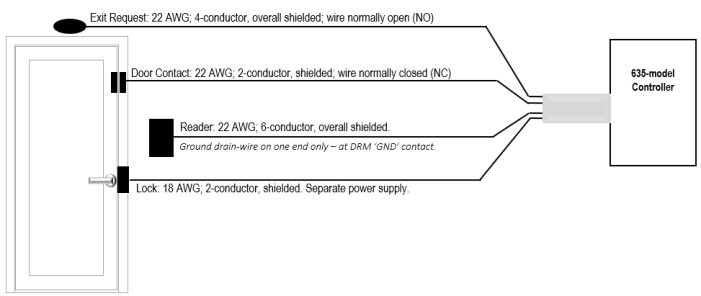
13.0 DOOR TOPOLOGY DIAGRAM
This diagram shows the Lock, Door Contacts, REX and Reader connected to the controller.
|
Connection Type |
Max Distance |
Wire Gauge & Specifications |
|---|---|---|
|
Request to Exit |
500 ft. from controller |
22 AWG; 4-conductor, overall shielded; wired normally open (NO) |
|
Door Contact |
500 ft. from controller |
22 AWG; 2-conductor, overall shielded; wired normally closed (NC) |
|
Lock Hardware |
500 ft. from controller |
18 AWG; 2-conductor minimum, shielded; Separate Power Supply. |
|
Refer to manufacturer’s instructions for device wiring (manufacturer's specs may supersede Galaxy specs). |
||
Jumper-out the following contacts, only if they are unused …
-
DRM board: If door contacts are not installed, you must jumper CNT to GND.
-
CPU board: If Low Battery wiring is not installed, you must jumper Low Batt to GND.
-
CPU board: If AC Fail wiring is not installed, you must jumper the AC Fail to GND.